
 Video coming soon
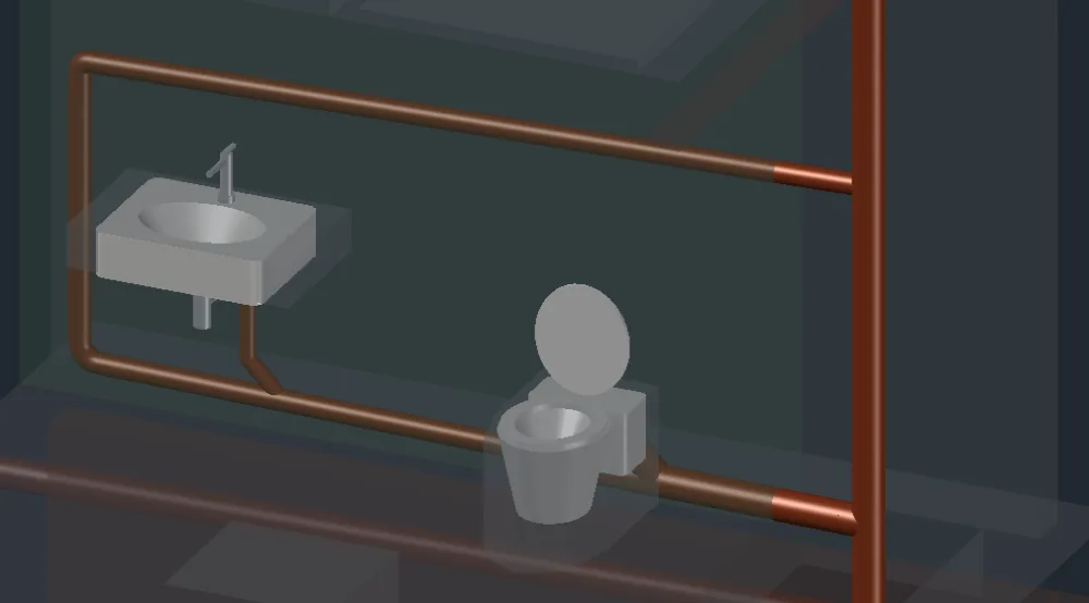
Drainage 3D: from connector to finished 3D network
Place connectors, draw the plumbing line, click Generate 3D – LuaCAD calculates slope, pipe sizes and fittings and builds the network in the system you choose.
 Video coming soon
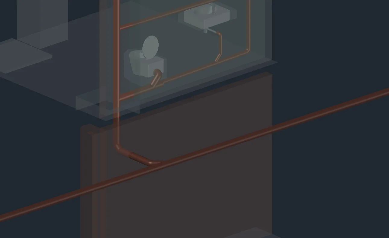
Fast routing – even in the in-wall carrier
Place fixtures and connectors in the floor plan; the plumbing line leads to the stack. Inside the in-wall carrier you route with dedicated tools: building drain, stack, connectors at the right height.
More in the online help →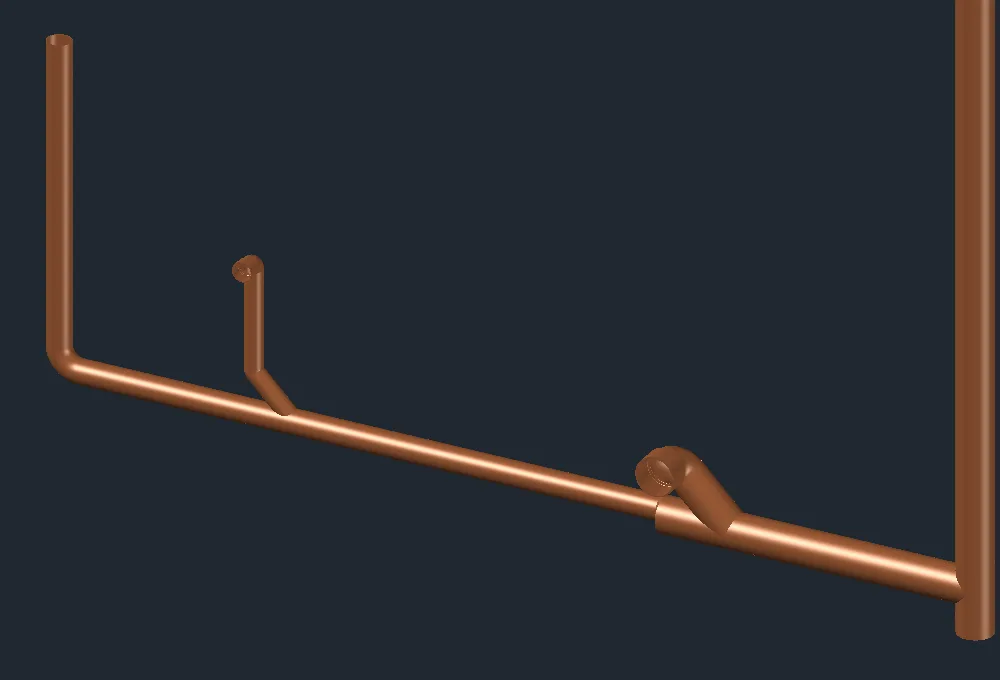
Generate 3D: slope and sizing, automatically
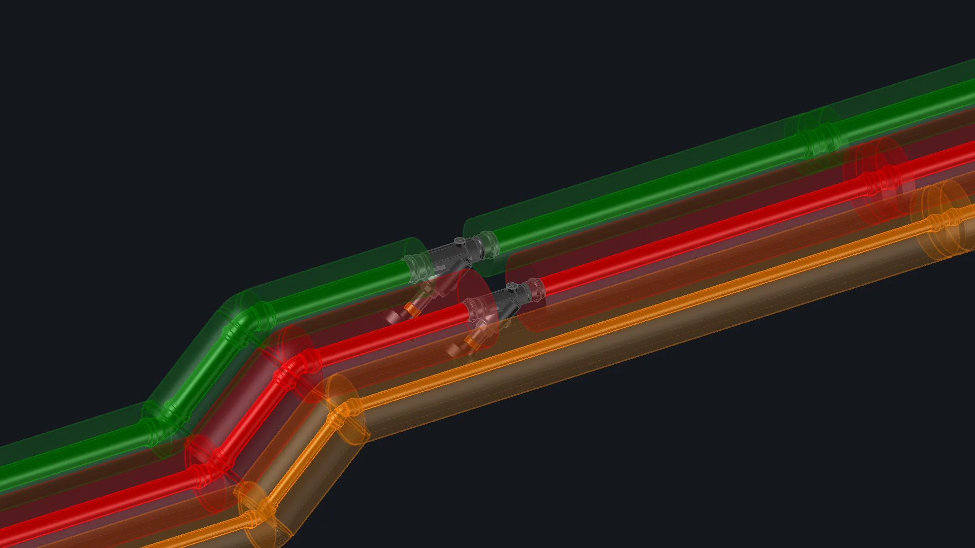
One click and the sketch becomes the pipe network: slope from your settings, pipe sizes from the calculation, wyes, elbows and offsets from the system catalog. Sizing notes appear in a list – Show takes you straight to the spot.
More in the online help →Standards and systems built in
Sizing follows DIN EN 12056-2 with DIN 1986-100, alternatively SN 592 000 or no standard. Push-fit systems (e.g. PP) and welded systems (PE with electrofusion couplings) are built in – including engagement lengths and weld loss.
- DIN EN 12056-2
- DIN 1986-100
- SN 592 000
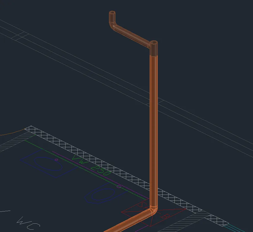
Across several levels
LuaCAD divides a stack across several levels into the drawings of each level – the load from above is included. If you move it, LuaCAD asks whether the other levels should follow.
More in the online help →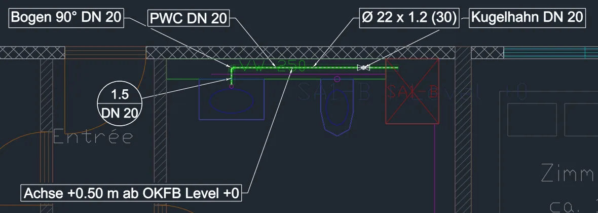
Annotation, spot elevations and lists
LuaCAD annotates pipes with material and diameter, plus slope and invert elevation – the annotation follows the pipe. Parts lists and bills of materials come from the same model, and the 3D network can be passed on as IFC.
More in the online help →Everything else in the online help
Step-by-step examples, every palette page and dialog box explained: the Drainage 3D help at help.luacad.com.
Drainage 3D help →
Try it yourself – free for 14 days
Choose LuaCAD 2D or LuaCAD 3D (3D includes 2D). GstarCAD Professional is included – free, no obligation.